
While we finish gathering responses to our virtual commissioning survey, let’s take a deeper look at how virtual commissioning looks with one of our most popular automation vendors – B&R Industrial Automation. Our video demonstration with B&R has been one of our most popular posts, so today, we’ll go into some more detail on each step in the process, for a virtual commissioning tutorial of sorts.
In the virtual commissioning tutorial below, you’ll be able to follow along with the process required to develop a digital twin, connect it to B&R Automation Studio, and to get model-based feedback as a controller is developed for a crane model. This process is what allows you to unlock the myriad benefits of virtual commissioning, and is similar technique that’s been used by industry leaders to fix issues on their existing machines.
Read on to see a technical description and virtual commissioning tutorial that uses tools from Maplesoft and B&R Industrial Automation. To see the full whitepaper that this tutorial was adapted from, visit maplesoft.com.
Virtual Commissioning Requirements
Virtual commissioning of a machine’s dynamics generally combines three important pieces: a digital model (sometimes referred to as a digital twin), the controller code that governs the motion and response to sensor feedback, and development environment that allows the two to be run together.
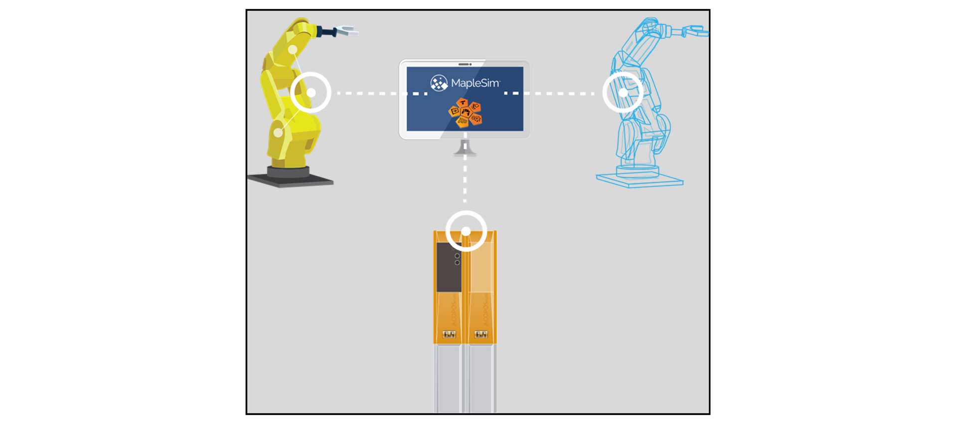 Figure 1: With tools like MapleSim and B&R Automation Studio, virtual models can connect with virtual control code, PLC hardware, and even the physical product itself.
1. Digital Twins: Physics-Based System Models
The digital model is a virtual representation of a corresponding physical product. It can be used to simulate, predict and analyze machine performance. These models can range widely in their purpose and fidelity, but they serve as a powerful connection to the product for diagnostics, design changes, and virtual commissioning. Companies are using digital twins across industries, allowing them to optimize their products in ways that were previously impossible.
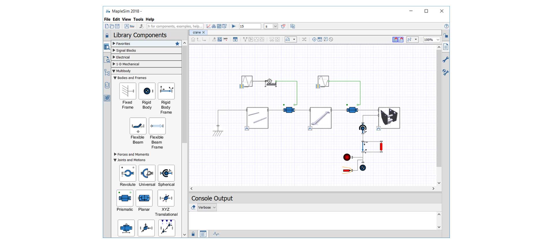 Figure 2: The Digital Twin, physics-based model in MapleSim.
For clarification, digital twins can also refer to predictive models that are created after a physical product is in operation. In these cases, data logged from sensors on the product are combined with machine learning algorithms to create a representative model of the machine. Although beneficial, these models cannot be used in the virtual commissioning workflow as they require the machine to already be constructed and commissioned (to obtain the data) before they can be used.
In contrast, by using a system-level modeling tool like MapleSim, the creation of a model-driven digital twin can begin alongside the design process. Meaningful digital twins can be created before a physical product is finalized, allowing for a powerful test platform to validate product performance earlier than ever, for important tasks such as sizing servo drives, motors, and gearboxes, as well as validating the mechanism design.
2. PLC Design
The second key piece of the virtual commissioning tutorial is the machine software. The performance of an automated machine is critically dependent on the nature of its control strategy. In operation, the physical machine is controlled by a PLC, which contains all of the necessary information to guide motion, respond to environmental feedback, and ensure that the machine functions properly in all situations.
 Figure 3: The design of a control strategy for an industrial machine often poses significant challenges when testing against the physical machine during the commissioning phase.
The design of machine code is often implemented in automation software, where users create control code on a virtual PLC. The control code is then deployed onto a physical PLC, and is connected to physical prototypes to test overall performance in the standard machine commissioning phase. This phase of design poses a large amount of uncertainty and risk, and issues found here can trigger rework, development delays, or machine damage. For these reasons, virtual commissioning can serve as an intermediate process to help identify issues before they’re found during physical machine testing. Furthermore, software implementation and tuning of control parameters can be performed in the office, avoiding expensive on-site commissioning. This thereby allows for improvements in software quality and reduces the time for implementation.
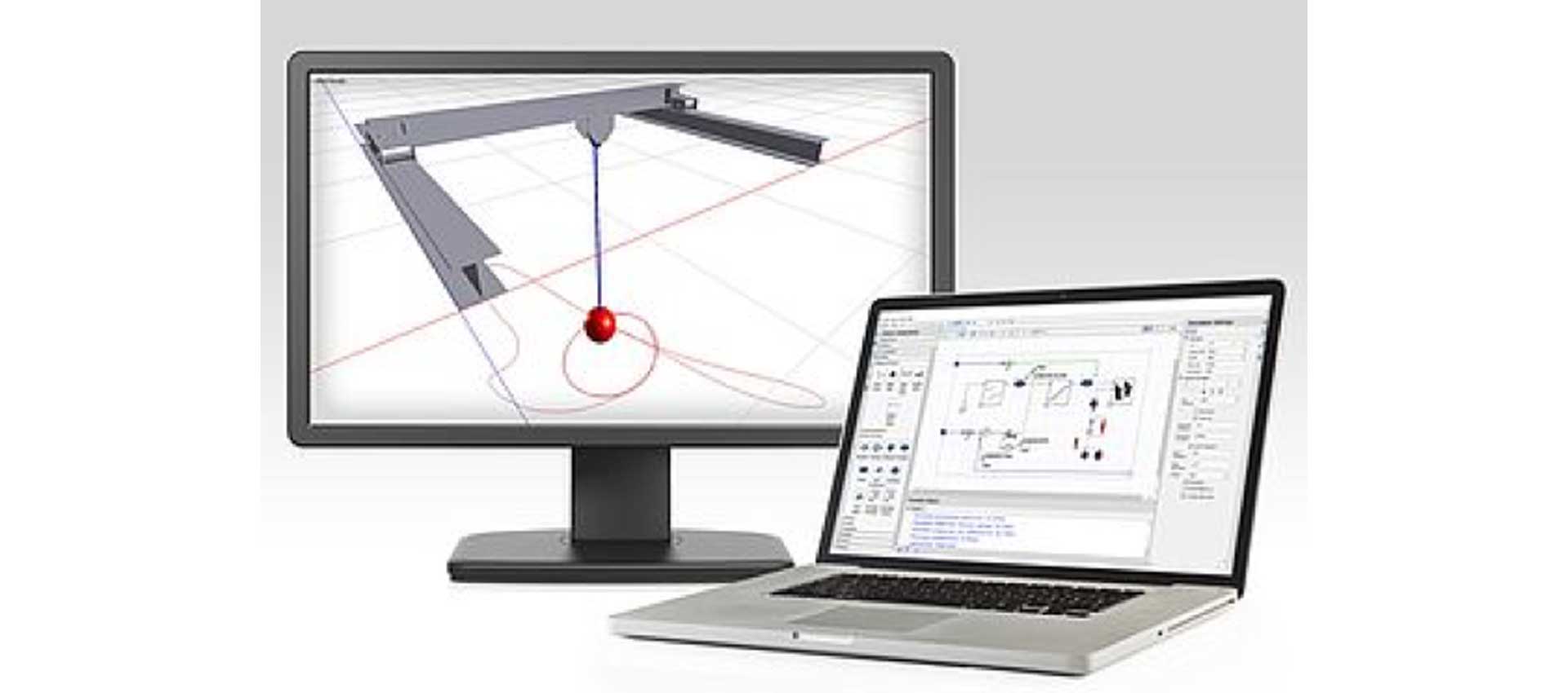 Figure 4: The B&R MapleSim Connector provides integration between digital twins created in MapleSim and the control software created in B&R Automation Studio.
3. The B&R MapleSim Connector
The final piece required for virtual commissioning is an environment, or workflow, that allows the machine software to be run against the digital twin. Historically, integrating system-level modeling and PLC design was challenging, if not impossible. The complex physics of a given digital model were typically simulated using a platform that operated differently than the logic-based systems of PLC design. In 2010, the Functional Mock-up Interface (FMI) was developed as a standard interface for a variety of model-based processes. The FMI standard is a collection of all the necessary information of a given model, organized in a way that allows for import and export with a variety of software tools.
The B&R MapleSim Connector is a tool that has taken the integration one step further, by providing a simplified workflow that connects digital twins with PLC design. Digital twins created in MapleSim can be exported as a Function Mock-up Unit (FMU) and used within B&R Automation Studio as a simulation-based test platform. All simulation information, including CAD data, is available within B&R Automation Studio, allowing control parameters to be analyzed and modified in real-time. This tool gives machine designers a new way to simulate, visualize, and validate their control strategy using a highly accurate model of their physical machine. With the included visualization, one can see directly how the machine behaves without first having to analyze complex traces or charts. This visualization allows for a better understanding of the system behavior and helps make the control development faster and easier.
Using the B&R Connector for MapleSim
To provide details on the virtual commissioning process, a demonstration workflow is presented below. In this example, the B&R MapleSim Connector is used to integrate a digital twin crane model with control testing in B&R Automation Studio. The crane model is created in MapleSim using CAD information and physics-based building blocks to describe the model dynamics. The model is then exported from MapleSim, and imported into B&R Automation Studio for control testing.
Creating the Crane Model
First, CAD data of the crane is imported. MapleSim supports a large variety of CAD formats from most major CAD platforms.
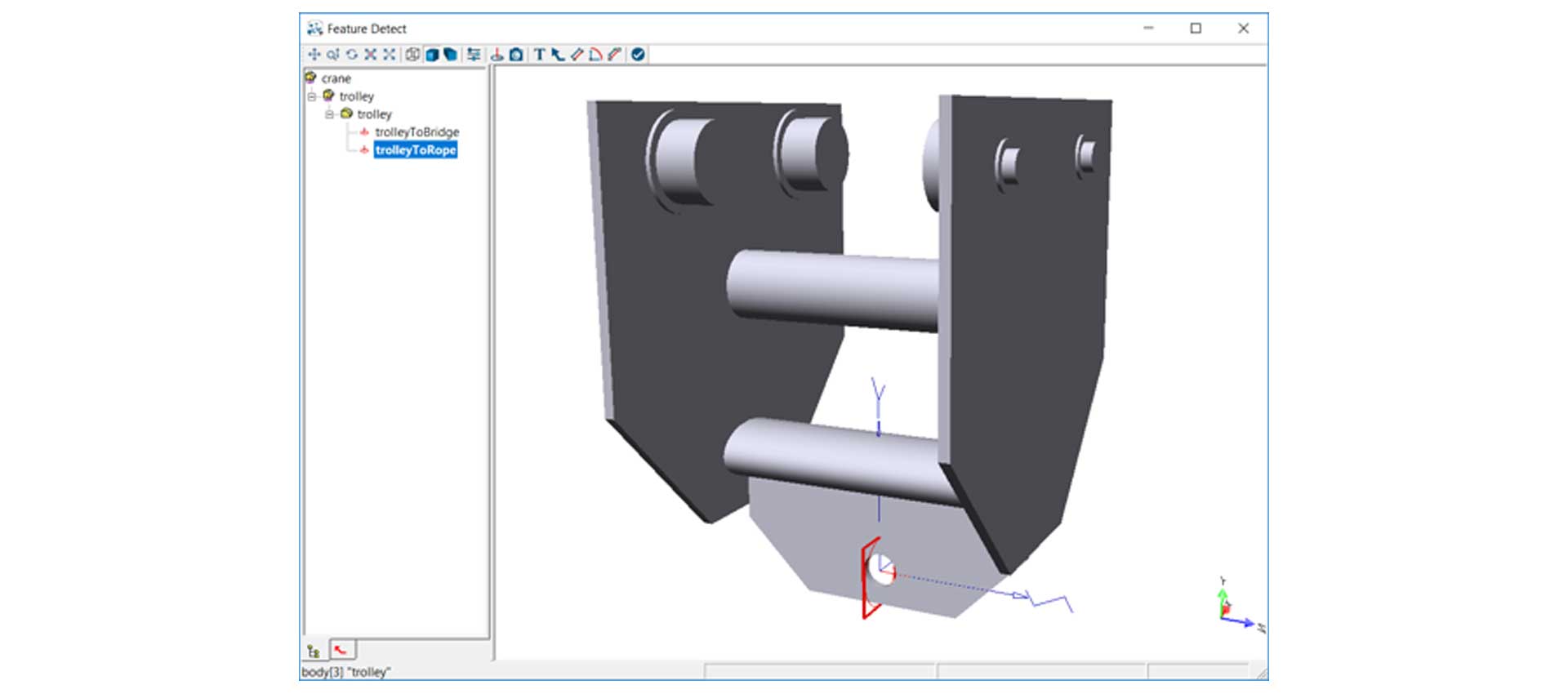 Figure 5: A subassembly of the imported CAD data.
During the import process you can add coordinate systems to the different CAD parts. After import, you can use the new CAD parts as MapleSim components and add other components to model the system dynamics. For example, two parts can be connected with a revolute or prismatic joint, and the two connection points at which the joint is fixed are defined by these coordinate systems.
By adding the various physical components to the original CAD parts, a complete physical system with moving parts can be created.
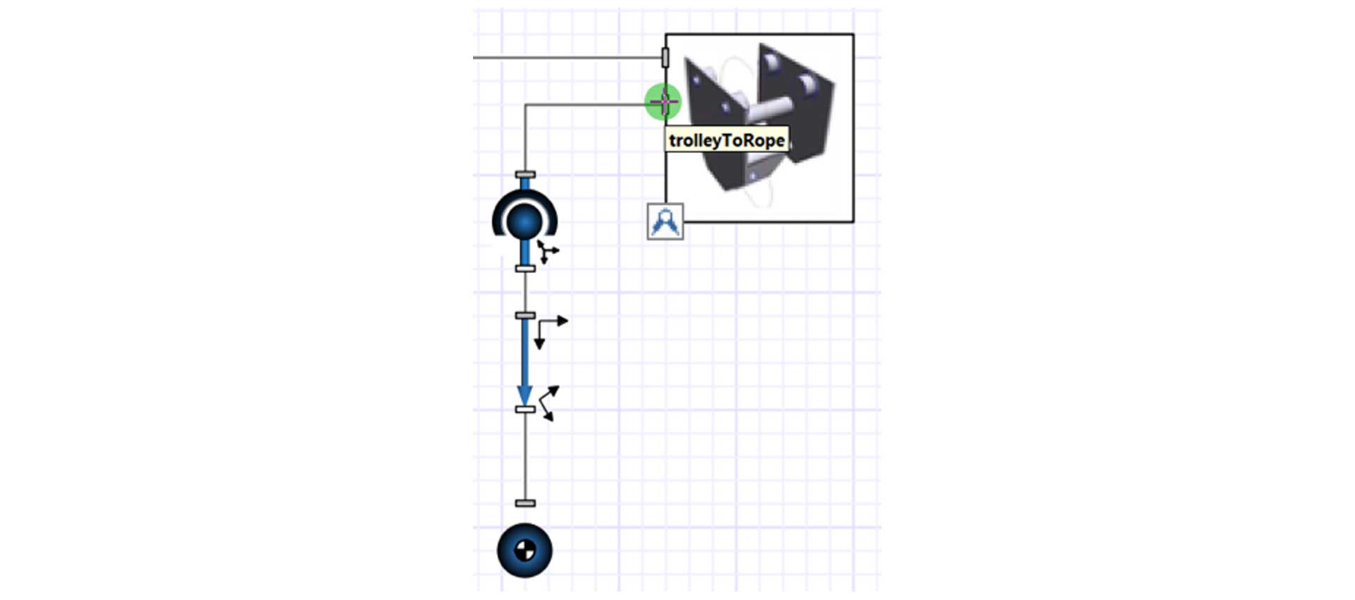 Figure 6: A part of the MapleSim model showing the combination of different physical parts
Animation of the Crane
Next, the created model can be visualized in the 3-D Playback window and be tested to show its physical behavior.
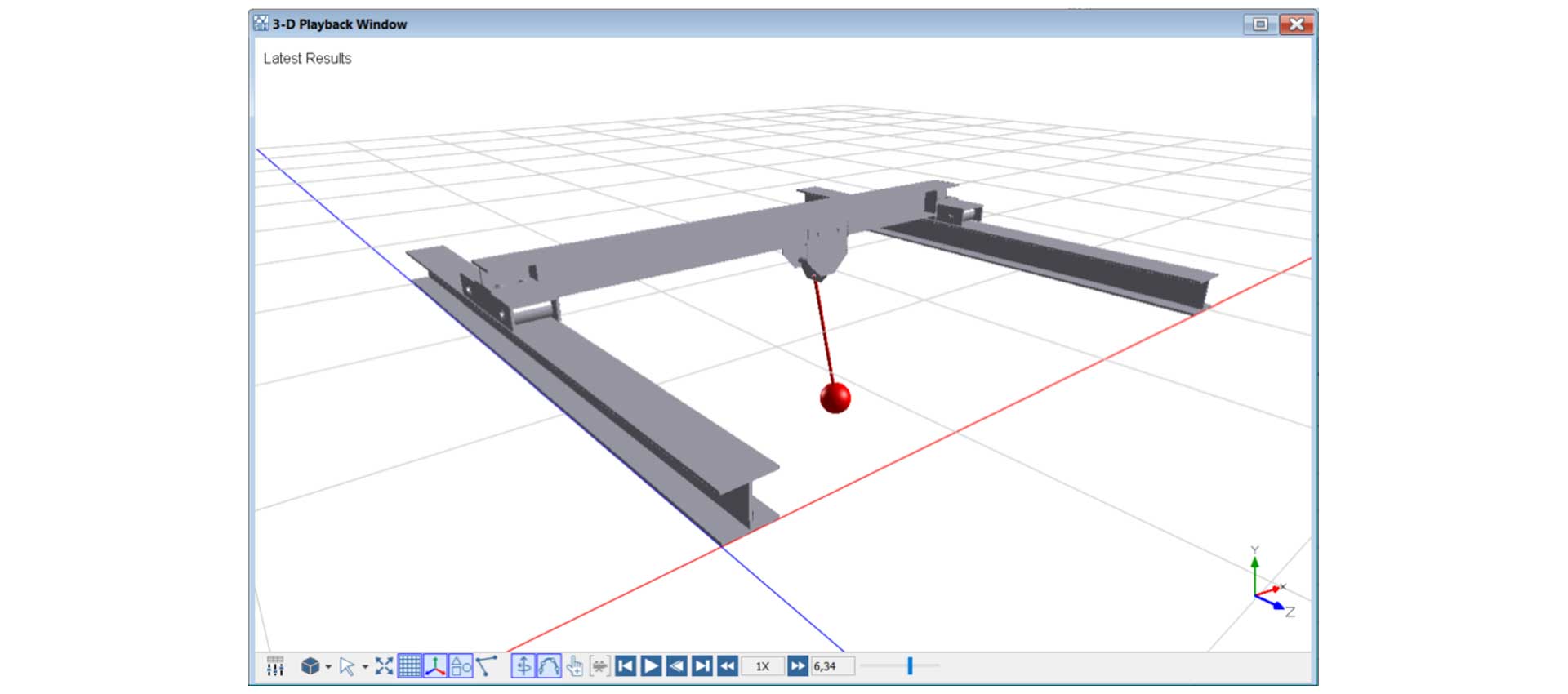 Figure 7: The visualized results of the crane model.
In addition to the visualization, the complete forces/torque required to generate a given motion can be investigated – and with the SERVOSoft Data Generation App (which comes with the B&R Connector), this information can be directly exported.
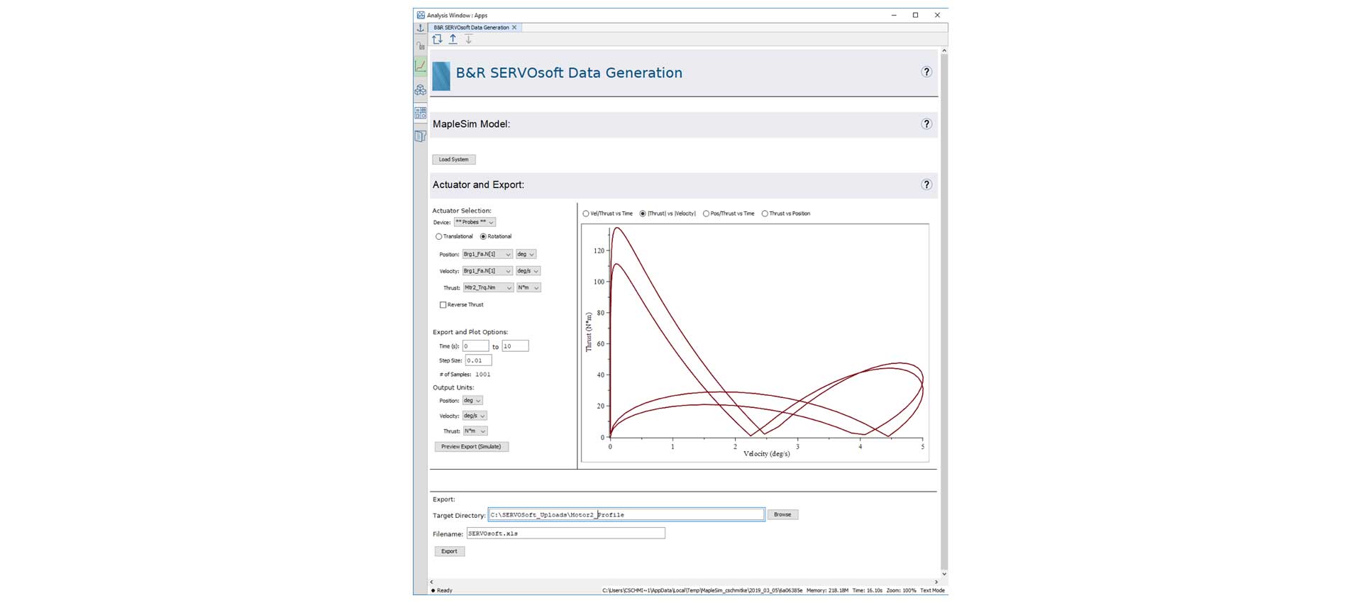 Figure 8: B&R SERVOSoft Data Generation App.
FMU Export to B&R Automation Studio
At this point, when the model is verified for correct behavior, it can easily be exported with the B&R Automation Studio FMU Generation App. Only a few parameters are needed to provide necessary information for a correct implementation into B&R Automation Studio.
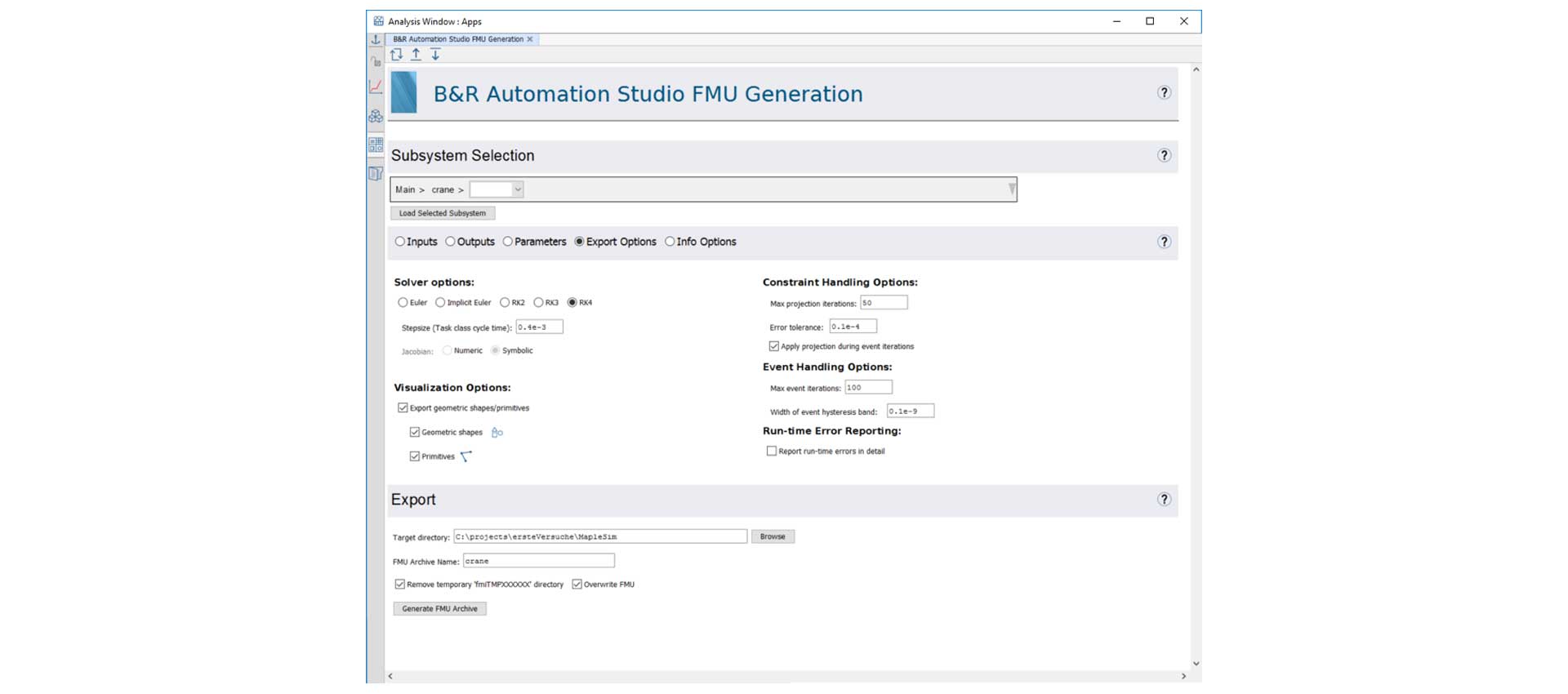 Figure 9: The B&R Automation Studio FMU Generation App.
Using the Crane Model in B&R Automation Studio
The created FMU library can be imported into B&R Automation Studio and subsequently be connected and simulated with a B&R PLC.
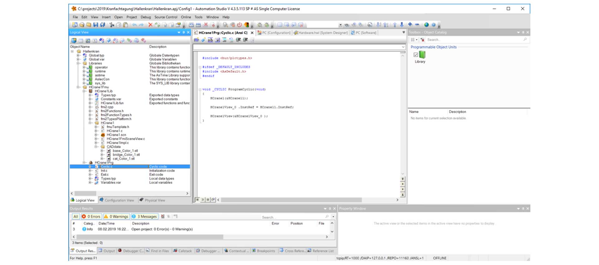 Figure 10: The FMU object from MapleSim included in B&R Automation Studio.
Thus, in B&R Automation Studio the complete system can be verified, starting from the physical behavior of the machine down to the program controlling its working sequence.
Finally, the visualization of the system is done in the B&R Scene Viewer.
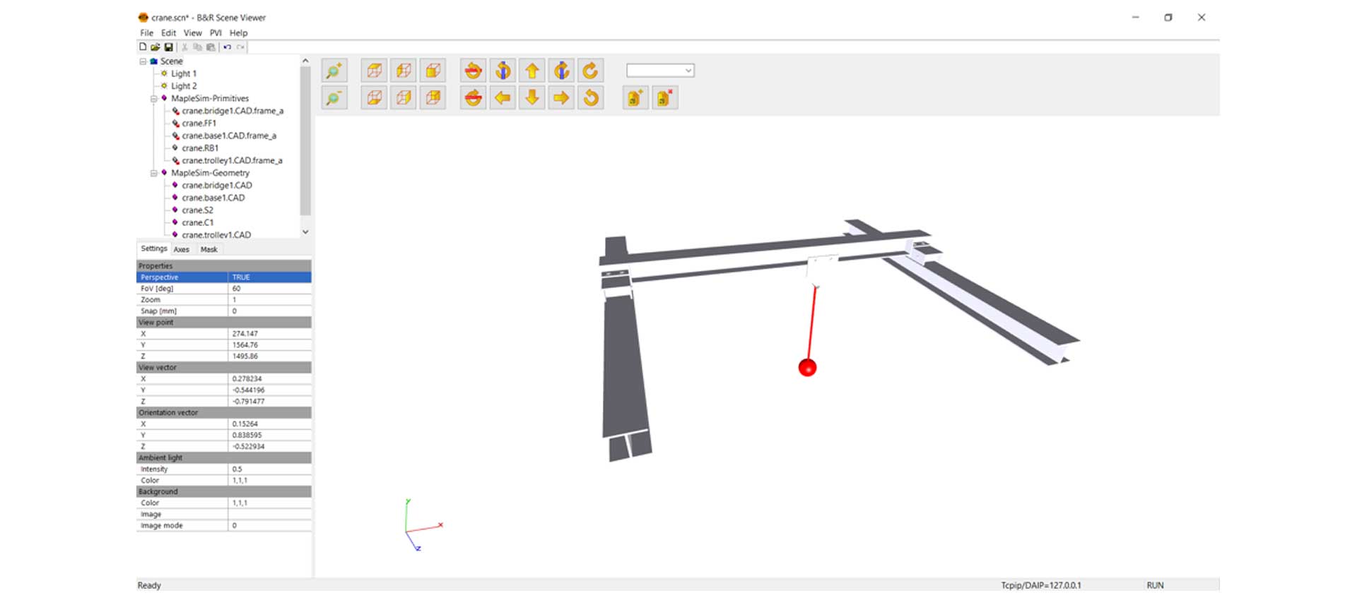 Figure 11: The B&R Scene Viewer showing the FMU of the physical system.
This virtual commissioning tutorial was adapted from a whitepaper from maplesoft.com.
You May Also Like

Fixing Machine Vibration Iss ...
15 September 2025

What is Virtual Commissionin ...
15 September 2025

Using Digital Twins to Corre ...
04 February 2025
Popular Post

Fixing Machine Vibration Issues for Less
September 15, 2025What is Virtual Commissioning?
September 15, 2025
Turnkey Solutions by Maplesoft

About the Editor